


|
HOW TO SPOT CHECK CAM TIMING
|
Quick Links:
|
Introduction
If you've ever installed a set of cams, did your best to line up the marks, and then stood back and scratched your head wondering if they're right, this article is written for you.
Sometimes cam marks leave room for interpretation. Many times I've found myself going back and forth, moving this cam or that cam a tooth each way, trying to figure out
if I've got them right or not, without going to all the trouble of attaching a degree wheel and dial indicators and making the measurements.
Then one day, many years ago, I mentioned this to a friend and mentor. Ron said something to the effect of "You @#$%! Aaron, why don't you just spot check your cam timing?", to
which I responded "Huh?".
"Just measure how much lift you have at overlap and compare it to the spec!" Too freakin simple.
So since then, whenever a set of cam marks leaves me wondering if it's right, I make some very quick and simple measurements to check my work. It could be done with a lot of precision if
you wanted to find true TDC and use more precise measuring methods, but you can make this measurement quick and dirty using crude tools and get precision that's much tighter
that one cam gear tooth. So it's a great method for verifying a cam installation. Really, all you need to do this is a 6" machinists ruler and a pocket calculator.
So here's the details on how I go about it. In a nutshell, we're going to measure the lifter position with the cams sitting on their base circle, and then we'll do the same with them sitting at overlap,
calculate the valve lift from these numbers, and then compare the answer to the cam specs. It matters not whether you do the base circle or the overlap measurement first.
|
Positioning the Motor
We're going to make two pairs of measurements, one pair at Compression TDC and another pair at Overlap TDC. So it's important to understand the difference between those positions and be
able to identify them. While that may sound basic to some of you, it's too important to ignore in this article. Particularly with procedures like pushrod adjustments, I can't count how many times
I've heard someone give advice to "position the motor at top dead center" without specifying which TDC they're talking about. Well, it's enormously important!
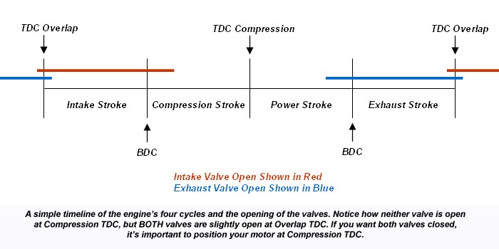
Study the above carefully and you'll see the obvious problem with the aforementioned advice. It takes two full revolutions of the motor for all 4 strokes to happen.
That means the piston passes through TDC twice. And yes, on one of those TDC's, both valves are closed (which is what you want for things like pushrod adjustments or removing/installing
rocker boxes), but on the other TDC, both valves are slightly open. So slightly, in fact, that it's very easy to mistake them for being closed. So unless you go through a process
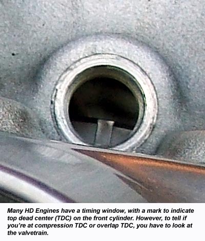
of turning the engine while watching the valvetrain, you have a very high chance of doing it wrong. Sure, many HD engines have a timing window and a mark on the flywheel to tell you when you're at
TDC, but it's up to you to figure out which TDC it is.
 To identify Compression TDC, watch your valvetrain as you rotate the motor in the forward direction. When you see the intake valve closing, you know you're on the compression stroke, as shown
in the drawing above. Continue until the intake valve is fully closed and then you reach TDC.
To identify Compression TDC, watch your valvetrain as you rotate the motor in the forward direction. When you see the intake valve closing, you know you're on the compression stroke, as shown
in the drawing above. Continue until the intake valve is fully closed and then you reach TDC.
For the purposes of measuring the lifter position while on the cam base circle, it's not critical that you're precisely at TDC. Technically, anywhere between where the intake valve closes (on the way up
the compression stroke) and where the exhaust valve opens (on the way down the power stroke) will work. Compression TDC is about halfway between those two events, so it's a nice safe place. The
valves move very slowly when they're near the seat, so to be absolutely sure both are in the closed position, it's safest to be at or near Compression TDC.
However, for the purposes of measuring the lifter position during overlap, how precisely we're positioned at Overlap TDC does matter. It takes very little movement away from Overlap TDC to change the
measurements pretty significantly. So pay close attention to positioning prior to that measurement.
If you don't have a timing window, or if you're working on the rear cylinder (most HD flywheels don't have a rear cylinder TDC mark), you need to determine TDC through the spark plug hole. Use something
that won't risk damage, for example a plastic straw works really well. Move the motor back and forth across TDC as you feel the straw for movement. The piston moves very slowly through TDC so this is a
little bit tedious, but it can be done. When you've convinced yourself the motor is halfway between where you can feel the straw move on each side of TDC, stop.
|
Measuring Lifter Position While on the Base Circle
OK, so you've got your motor somewhere near Compression TDC as described above. We're going to now make a simple, crude measurement of the valvetrain position.
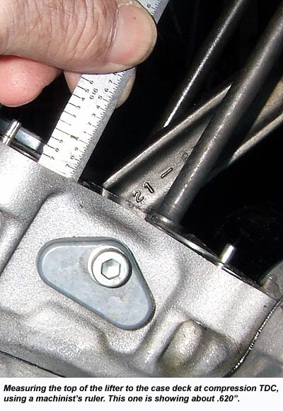 There are various places and ways to make this measurement, depending on the accuracy needed and the access you have available. Shown here is one of the best places to do it,
if you have access, which is between the case deck and the top of the lifter. The measurement can be made with a simple machinist's ruler as shown, or assuming the heads aren't
in the way, it can also be done with a dial or vernier caliper positioned as a depth gauge. The machinist's ruler has graduations to ten one-thousandths of an inch (.010"),
and this is adequate for what we're doing. A caliper can typically read to one one-thousandth of an inch (.001") though, so it's the preferred way to make the measurement,
assuming you have both the caliper and the access.
There are various places and ways to make this measurement, depending on the accuracy needed and the access you have available. Shown here is one of the best places to do it,
if you have access, which is between the case deck and the top of the lifter. The measurement can be made with a simple machinist's ruler as shown, or assuming the heads aren't
in the way, it can also be done with a dial or vernier caliper positioned as a depth gauge. The machinist's ruler has graduations to ten one-thousandths of an inch (.010"),
and this is adequate for what we're doing. A caliper can typically read to one one-thousandth of an inch (.001") though, so it's the preferred way to make the measurement,
assuming you have both the caliper and the access.
I've even done this with the pushrods and valvetrain completely installed, when the motor was equipped with collapsible pushrod covers. Sometimes I'll line up the case deck
by sight and put a reference mark on the pushrod itself, and then later when I do the Overlap TDC measurement, I measure how far that mark has moved up away from the case deck.
But even with pushrod covers in the way, it's possible to do a similar kind of measurement up at the rocker box. Just precisely make a mark on the pushrod or rocker arm,
referenced to something that's not going to move. When you make the Overlap TDC measurement, simply measure how far it has moved.
Of course, in the ideal situation, we'd make this measurement at the valve itself, and that's certainly possible. But it's typically in a difficult to access place on an HD
motor, particularly one that's installed in a frame.
However you do the measurement, write down the numbers, and repeat the measurement for the exhaust side as well.
|
Measuring Lifter Position While on Overlap
Turn the motor one full rotation from Compression TDC to put it at overlap TDC.
 Remember, for this measurement, the position of the motor is critical. It's not like the Compression TDC measurement, where the motor just has to be somewhere near TDC.
Even a very little bit of motor rotation will change your measurement pretty significantly. This can especially be a problem when you're dealing with an assembled valvetrain,
as the valve spring pressure may very well want to rotate the engine away from where you want it. You can always put it in gear and lock the back brake to hold everything still.
Remember, for this measurement, the position of the motor is critical. It's not like the Compression TDC measurement, where the motor just has to be somewhere near TDC.
Even a very little bit of motor rotation will change your measurement pretty significantly. This can especially be a problem when you're dealing with an assembled valvetrain,
as the valve spring pressure may very well want to rotate the engine away from where you want it. You can always put it in gear and lock the back brake to hold everything still.
There's another issue, though, about making this measurement with an assembled valvetrain. If you have stock hydraulic lifters, the valve spring pressure is applied to the
lifter plunger, which is slowly making it go down as the oil "bleeds" out of it. Well, if you're taking your measurement at the pushrod, or upstairs somewhere in the cam box, that
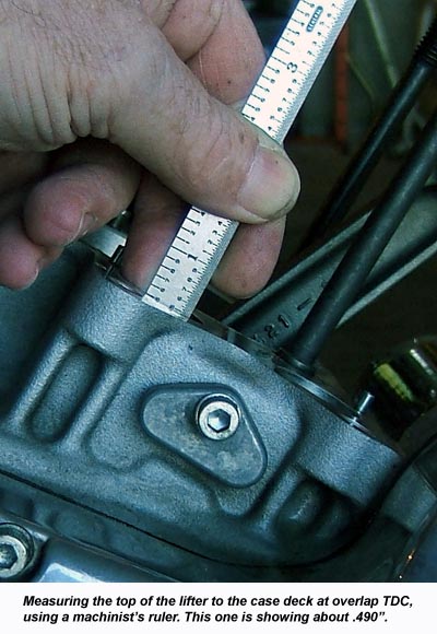
bleed down effect is changing your measurement. Either you've got to be very quick positioning the motor and then making the measurement, or you should make the measurement as I've done here,
which is not at the plunger itself, but rather at the perimeter of the lifter.
But if you're doing this measurement as a preventive measure after installing cams, then there shouldn't be any valve spring pressure applied yet. Of course, if you're doing this
measurement because you think you might have done it wrong and the motor didn't run correctly, the damage is probably already done and the rocker boxes will have to come off anyway.
Again, write down your measurement, and repeat the process for the exhaust side.
|
Doing the Math
OK, so we've taken our lifter position measurements, now we just run the numbers.
It's fairly obvious that lobe lift is just the difference between the two numbers for a given lifter. In the example pictured, I measured .620" on the base circle and .490" on overlap
for the intake lifter. .620" minus .490" tells me I have .130" of lobe lift on the intake side.
Not pictured, but trust me, my exhaust lifter position also measured .620" on the base circle, but it came up more like .500" on overlap. .620" minus .500" tells me I have .120" of lobe
lift on the exhaust side.
Before I go grab the spec sheet on the cams and compare, though, I have to remember that these are lobe lifts, not valve lifts. The TDC lift specifications for the cams are given
in valve lift though. So I have to convert. That's pretty simple, though, just multiply by the rocker arm ratio, which is 1.625 for HD all Evo and later HD air cooled motors:
.130" intake lobe lift times 1.625 equals .211" of intake valve lift
.120" exhaust lobe lift times 1.625 equals .195" of exhaust valve lift
So my quick and dirty measurements come up with TDC lifts of .211/.195".
This motor is equipped with Screamin Eagle bolt-in cams, as came stock on many Buell models. So a quick visit to the Cams and Valvetrain page
on the Hammer Performance web site reveals the following:
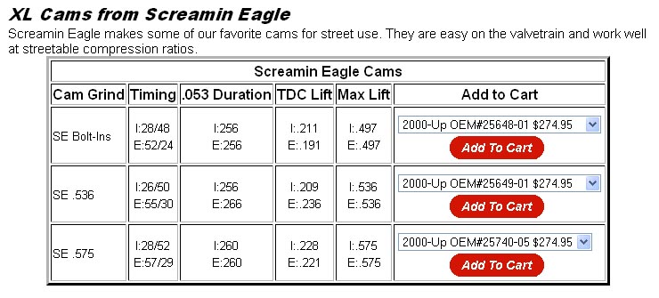
Our cams are the first entry in this table. As shown, the TDC lift specs for these cams are .211" intake and .191" exhaust, both of which are very close to the .211" &.195" we measured.
So it's safe to say our cams are installed correctly.
For the measurements to come out this close is a bit unusual, although they truly did come out this way for me as I walked through the process to take pictures for this article. More often
than not, your measurements will be slightly higher than spec on one side and slightly lower than spec on the other side, which can be explained mostly by lack of precise Overlap TDC positioning.
For example, if the intake in this example was to come out at say .220", and the exhaust at say .180", more than likely it would mean that the Overlap TDC measurements were taken with the
motor turned just a little too far, because at overlap TDC the intake is opening and the exhaust is closing. Likewise, a lower than spec intake TDC lift coupled with a higher than spec exhaust TDC lift would mean
that more than likely, the Overlap TDC measurements were taken with the motor not quite turned enough. The important thing, though, is that both measurements are reasonably close to spec, and
that they make sense in terms of one being low while the other is high.
Even one tooth off on a cam is enough to put a measurement out in the weeds, and it will be very obvious. So this method, while quick and dirty and not terribly precise, is still very
useful to verify the cams are installed correctly.
|
|
|
|

|
|
|